
Disaster Recovery with OADP on ROSA HCP
This content is authored by Red Hat experts, but has not yet been tested on every supported configuration. This guide has been validated on OpenShift 4.22. Operator CRD names, API versions, and console paths may differ on other versions.
This guide demonstrates a complete disaster recovery (DR) solution for ROSA HCP using OADP (OpenShift API for Data Protection), S3 Cross-Region Replication, EFS replication, and Route 53 DNS failover. You will deploy a demo application, configure backup and restore infrastructure, and walk through two DR scenarios: hot-to-warm failover and cold DR failover.
Architecture Overview
- Primary cluster in Region A (e.g. us-east-1), DR cluster in Region B (e.g. us-west-2)
- S3 with Cross-Region Replication for application data and OADP backups
- EFS with Cross-Region Replication for persistent volume data
- Route 53 failover routing with health checks for automatic DNS failover
Prerequisites
- Two ROSA HCP clusters (one per region), referred to as
PRIMARY_CLUSTERandDR_CLUSTER - AWS CLI,
ocCLI,rosaCLI,helmCLI - A Route 53 hosted zone (optional, for custom domain failover)
- The AWS EFS CSI Driver Operator installed on both clusters. Follow Enabling the AWS EFS CSI Driver Operator on ROSA to set up EFS CSI on each cluster.
Environment Variables
Set these variables for your environment. You will need values from both clusters.
Get the OIDC endpoints for both clusters:
Get the VPC and subnet info from the machine pools (the worker node subnets are in your account):
Set the S3 bucket names:
Step 1: Create S3 Buckets with Cross-Region Replication
Create the application data and OADP backup buckets in both regions with versioning enabled:
Create an IAM role for S3 replication:
Configure replication rules for both bucket pairs:
Step 2: Create EFS with Cross-Region Replication
Create the primary EFS file system
Create a security group for EFS in the primary region:
Create the EFS file system:
Create mount targets in all machine pool subnets so pods in any AZ can access EFS:
Configure cross-region replication to the DR region:
Get the replica EFS file system ID:
Configure security groups for the DR region
Create a security group for EFS in the DR region:
Add NFS ingress rules allowing traffic from the worker security groups on both clusters:
Create mount targets on the DR replica
Create mount targets on the DR replica file system so it is ready for failover. Mount targets can be created on a read-only replica — they will be functional once the replica is promoted to read-write during failover.
Install the EFS CSI Driver
Install the AWS EFS CSI Driver Operator on both clusters. You can automate this with the provided script or follow the manual guide .
Option A: Automated install (recommended)
Download and run the install script on each cluster. The script prompts for the cluster name and auto-detects the remaining values.
Run the script once while logged into the primary cluster, then again while logged into the DR cluster.
Option B: Manual install
Follow Enabling the AWS EFS CSI Driver Operator on ROSA . Complete these sections from the guide on each cluster:
- Set environment variables
- Create the IAM policy and role - creates the IAM role for the CSI driver operator
- Install the AWS EFS CSI Driver Operator - installs the operator via the web console
- Create the ClusterCSIDriver - enables the CSI driver pods
- Find worker subnets, VPC, security groups, and IAM roles - only the worker IAM role name is needed from this section
- Attach EFS permissions to the worker role - attaches the EFS CSI policy to the worker role
Stop after Attach EFS permissions to the worker role. Do not continue to “Create an EFS security group” or beyond.
Create the EFS StorageClass
Create the StorageClass on both clusters. Use directoryPerms: "755" so that EFS-provisioned directories are readable by any UID — this is required for DR because the DR cluster’s pods run under a different UID range than the primary.
On the primary cluster:
On the DR cluster:
Step 3: Create IAM Roles
Application S3 access roles
Create IAM roles for the demo application to access S3 from both clusters. These roles use IRSA (IAM Roles for Service Accounts) with the ROSA HCP OIDC provider.
Create the S3 access policy:
Create the role for the primary cluster:
Create the role for the DR cluster:
OADP/Velero roles
Create IAM roles for OADP on both clusters.
Create the OADP policy:
Create the OADP role for the primary cluster:
Create the OADP role for the DR cluster:
Step 4: Install OADP on Both Clusters
Repeat these steps on both the primary and DR clusters.
Install the OADP Operator
Create the openshift-adp namespace and install the OADP Operator:
Wait for the Operator to install:
Create credentials and DataProtectionApplication
Repeat this section on both clusters, using the appropriate values for each.
On the primary cluster:
On the DR cluster:
Verify the Backup Storage Location is available on each cluster:
The PHASE column should show Available.
Step 5: Deploy the Demo Application
Deploy the Phoenix Mission Control demo application on the primary cluster.
Clone the Helm chart:
Install the application on the primary cluster:
Verify pods are running:
Access the dashboard:
Open the route URL in your browser to verify the application is working.
Record EFS Path Mapping for DR
After the application is deployed and the PVCs are bound, record the EFS access point paths for each PVC. This mapping is essential for DR — it tells the static PVs on the DR cluster where the replicated data lives. Record these values and store them securely as part of your DR runbook. Update this mapping any time PVCs are recreated.
On the primary cluster:
Save the output as part of your DR runbook. The demo application uses 3 EFS-backed PVCs:
shared-flight-data— shared volume mounted by the dashboard and flight recorderflight-data-flight-recorder-0— StatefulSet replica 0flight-data-flight-recorder-1— StatefulSet replica 1
The variables are automatically exported in your current shell. To re-export in a new session, paste the export lines from the output.
Step 6: Configure Route 53 DNS Failover (Optional)
This step sets up automatic DNS failover using Route 53 health checks and failover routing.
Get the router ELB hostnames from both clusters.
On the primary cluster:
On the DR cluster (the app is not deployed yet, so get the default router hostname from the ingress controller):
On the primary cluster:
Get the application route hostname on the primary cluster (this is the hostname the health check will probe, not the generic router hostname):
Create a health check on the primary route:
Create the PRIMARY failover CNAME record:
Create the SECONDARY failover CNAME record:
Create a TLS certificate for the custom domain using Let’s Encrypt with the certbot-dns-route53 plugin. This uses DNS validation, so you don’t need to expose a web server.
Request the certificate. Certbot uses your AWS credentials to create a temporary TXT record in Route 53 for domain validation:
Set the certificate paths:
Add the custom domain route on both clusters:
Verify the Application
Before testing DR scenarios, verify the application is running and accessible through your custom domain. Open https://<your-custom-domain> in a browser.
You should see the Mission Control dashboard:
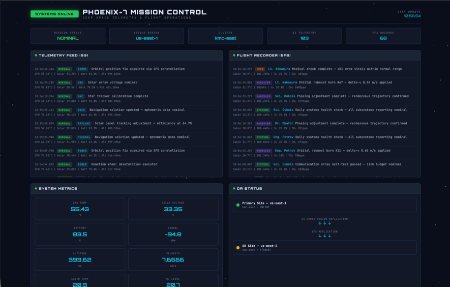
Confirm that telemetry data is being recorded and that the S3 connection is healthy before proceeding with DR testing.
DR Scenario 1: Hot-to-Warm Failover
Both clusters have running worker nodes, but the application is deployed only on the primary cluster. This is the fastest failover scenario.
Failover (Primary to DR)
Create an OADP backup on the primary cluster:
Wait for the backup to complete:
Wait until the output shows Completed.
Sync the backup to the DR bucket. Although S3 Cross-Region Replication is configured, it is asynchronous and may lag. The manual sync ensures the backup is immediately available for a time-critical restore:
Verify that EFS replication is healthy and review the most recent replication timestamp before promoting the DR file system:
Confirm that the replication status is ENABLED and that LastReplicatedTimestamp meets your recovery point objective before proceeding. Data written after the last replicated timestamp might not be available on the DR file system.
Delete EFS replication to promote the replica to read-write:
Wait for the DR file system to finish promoting to read-write. Pods that try to mount the EFS before this completes will fail with mount errors:
On the DR cluster
Log in to the DR cluster and wait for Velero to sync the backup (this happens automatically within a minute):
Create static PVs that point to the replicated EFS data. These must exist before the restore so that the restored PVCs bind to them immediately — preventing the StatefulSet controller or dynamic provisioner from creating new volumes. The claimRef pre-binds each PV to the expected PVC name:
Create the restore. PVs are excluded because we created our own above. PVCs are included — Velero restores them with restorePVs: false, which clears their volumeName so they bind to the pre-existing PVs via claimRef:
Wait for the restore to complete:
Verify that PVCs are bound to the static PVs:
Update the service account annotations and environment variables to use the DR cluster’s IAM role and region. The restore brings over the primary cluster’s values, which must be updated for the DR cluster’s OIDC provider:
To simulate a primary site failure, disable auto-repair on the primary cluster’s machine pool and stop the worker instances:
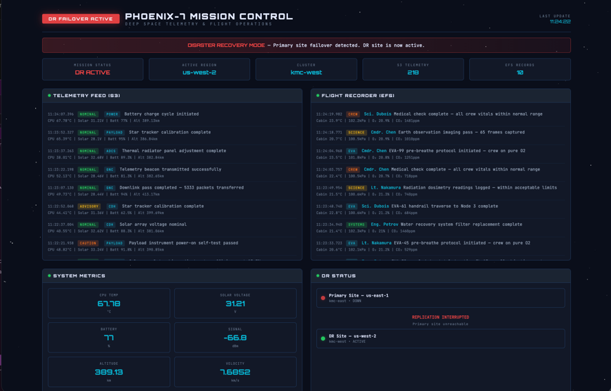
Once the primary workers are down, the Route 53 health check will fail and DNS will automatically route traffic to the DR cluster. Open the Mission Control dashboard at your custom domain URL to confirm the failover. The dashboard shows the primary site is down and the DR site is now active:
Failback to the Primary Cluster
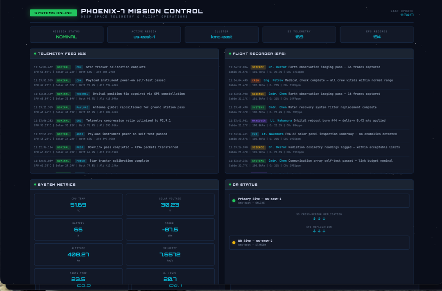
In the hot-to-warm scenario, the primary cluster’s application was never deleted - only the worker nodes were stopped. To fail back, restart the primary workers:
Once the workers are running, the application pods resume automatically.
Before allowing production traffic to return to the primary cluster, verify that the application is healthy and that any required DR-side EFS and S3 data has been reconciled. Application health alone is not sufficient to determine that a stateful workload is ready for failback.
After validation, Route 53 can return traffic to the primary cluster when the health check reports it as healthy.
Re-establish EFS replication from primary to DR so it is in place for future failovers. First, disable the overwrite protection that AWS enables on the replica after replication is deleted:
DR Scenario 2: Cold DR (Scaled-Down DR Cluster)
In this scenario the DR cluster’s worker nodes are stopped to save costs. Starting the instances is required before the restore can proceed.
Setup: Scale Down DR Cluster
Delete the dr-demo namespace on the DR cluster to start with a clean state, and remove any static PVs left over from a previous failover (PVs are cluster-scoped and survive namespace deletion):
Stop the DR cluster worker nodes to reduce costs during normal operation:
Failover to Cold DR
The backup already exists in S3 from when the primary was running (created in Scenario 1 or by a scheduled backup). S3 Cross-Region Replication has copied it to the DR bucket.
Verify the backup is available in the DR bucket:
Set the backup name to the most recent valid backup:
If CRR has not finished replicating the backup, manually sync it:
Simulate a primary region outage by stopping the primary cluster’s worker instances:
Verify that EFS replication is healthy and review the most recent replication timestamp before promoting the DR file system:
Confirm that the replication status is ENABLED and that LastReplicatedTimestamp meets your recovery point objective before proceeding. Data written after the last replicated timestamp might not be available on the DR file system.
Delete EFS replication to promote the replica to read-write:
Wait for the DR file system to finish promoting to read-write. Pods that try to mount the EFS before this completes will fail with mount errors:
Start the DR worker instances:
Wait for Velero to be ready (it will automatically reschedule when the nodes are available):
Create static PVs that point to the replicated EFS data before restoring. The claimRef pre-binds each PV to the expected PVC name so that restored PVCs bind immediately:
Restore from the backup. PVs are excluded because we created our own above. PVCs are included — Velero restores them with restorePVs: false, which clears their volumeName so they bind to the pre-existing PVs via claimRef:
Wait for the restore to complete and the namespace to be available:
Verify that PVCs are bound to the static PVs:
Update the service account annotations and environment variables for the DR region:
DNS failover happens automatically via the Route 53 health check. If you did not configure Route 53, update DNS manually to point to the DR cluster.
Once the pods are running and DNS has updated, you should see the application running on the DR cluster:
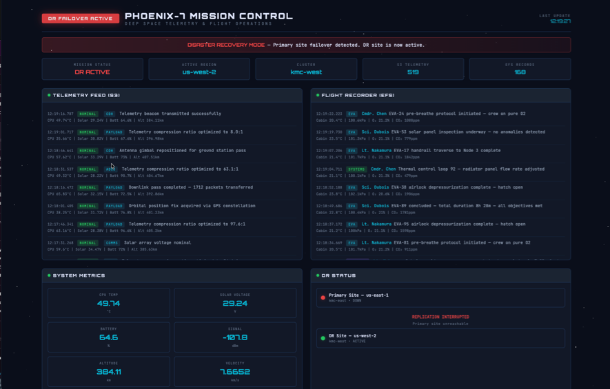
The result is the same as Scenario 1, but the failover takes longer because the DR cluster was scaled down to zero and the worker instances had to be started before the restore could proceed.
Cleanup
Remove all resources created by this guide.
Delete the demo application on both clusters
Delete the OADP Operator on both clusters
Delete S3 buckets
Delete EFS file systems
Delete any remaining replication configuration, mount targets, access points, and the file systems:
